Feature
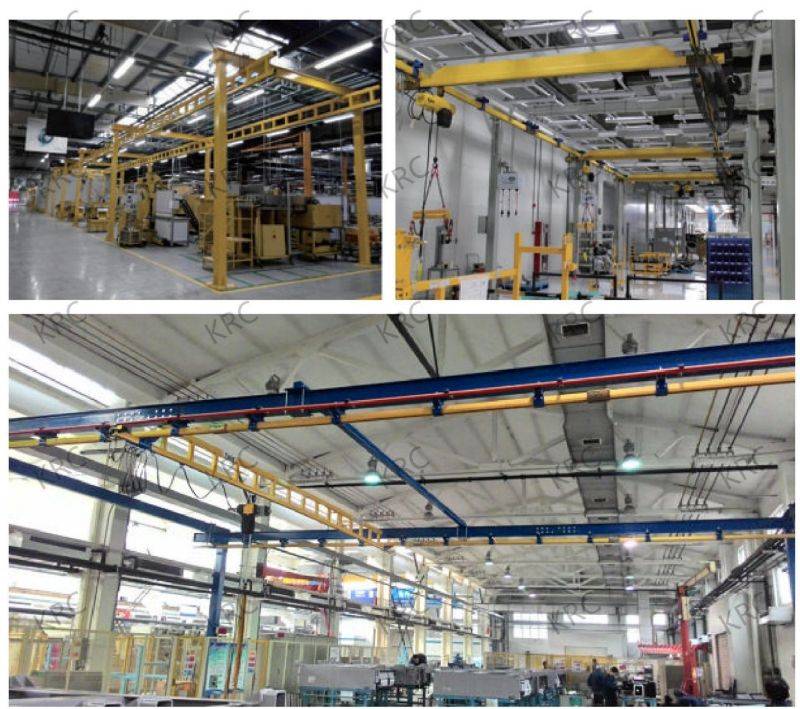
Our KBK Rigid Track System is both economical and effective, with a rated load capacity of up to 2000 kilograms and a span of up to 10 meters. The modular design allows for easy scalability and cost-effectiveness. Various support brackets facilitate easy installation, making it adaptable to future or existing suspension conveying systems. Telescopic boom cranes are available for both manual and electric operation, and the system can be ground-mounted or ceiling-suspended. Product components can also be plated with gold or silver for enhanced durability and aesthetics.
The track system comes in three sizes to accommodate different lifting capacities, with a maximum load of 2000 kilograms. The slope design of the track ensures the straightness of the pulleys inside, reducing dust accumulation and prolonging the track’s service life. Only 1-4% of the load capacity is required to operate the KRC light crane, making it highly efficient.
Types of KBK Crane Systems
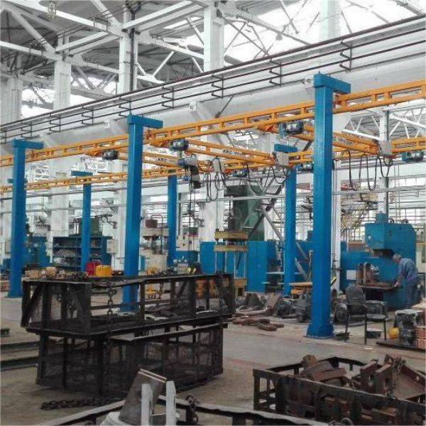
Self-Powered Crane
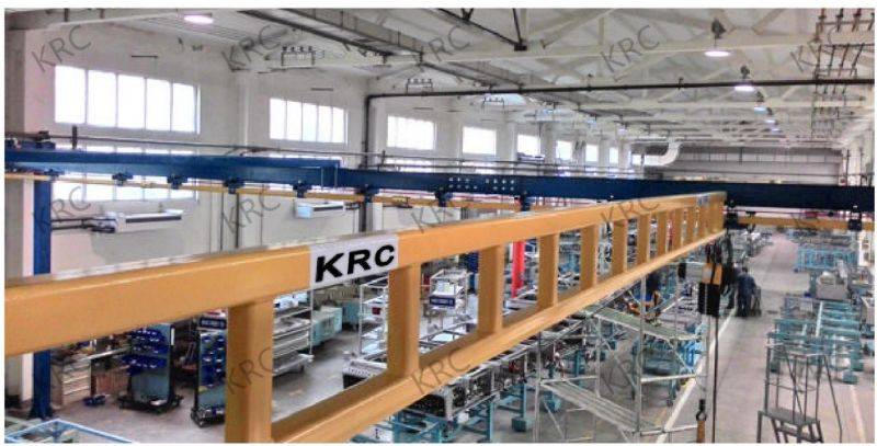
Available in both ordinary and truss-type tracks, the main beam of the ordinary track usually uses reinforced racks, while the truss-type track increases the spacing between support suspension points, simplifying installation.
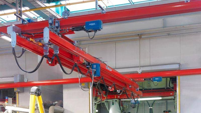
Suspension Crane
This type comes in ordinary and truss-type tracks. The ordinary track is directly fixed to the top parallel I-beams, whereas the truss-type track reduces the number of lifting points required when the top lifting steel structure is limited.
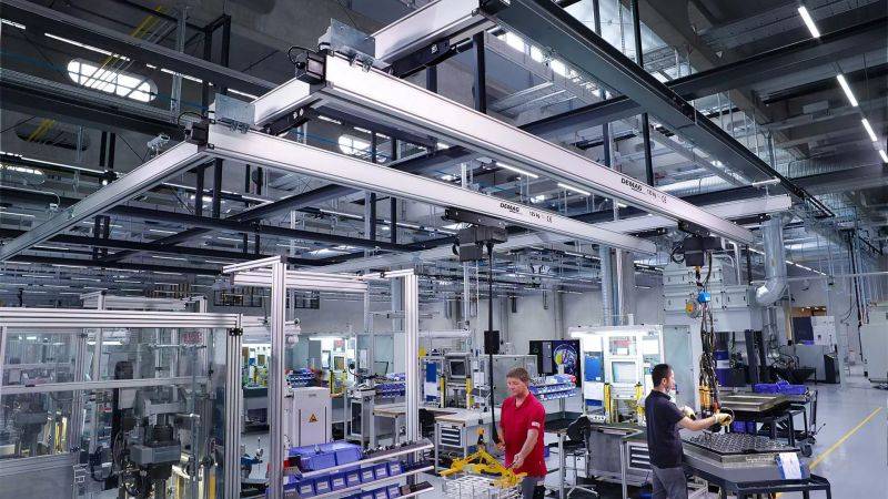
Multi-Beam Crane
Ideal for scenarios where multiple operators need to work simultaneously in the same area. Various buffer zones prevent interference between the main beams, using track end stops, isolation rods, or mobile buffer zones.
Telescopic Monorail System and Crane
Used when the effective coverage area of a light crane exceeds the range of its supporting structure. This system is commonly used on containers, trucks, or in the automotive industry.
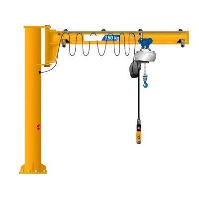
Jib Crane
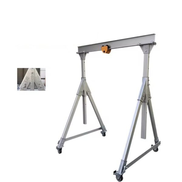
Provides high-quality and low-cost cantilever cranes in both wall and column support forms. With a maximum load capacity of 1000 kilograms and a rotation angle of 180 degrees, the enclosed track design makes operation easy with minimal pulling force required.
Module
Power Supply System
The suspension cable system equipment includes all necessary components for installing the power supply, featuring a 4x 2.5 mm² PVC flat cable suitable for all electric hoists with a power consumption of less than 25A. The system includes roller and shaft sleeve connected by rolling ball bearings, galvanized C-rail, rack support frame, and track connector. Options include support arms and clamps for connecting crossbeams and longitudinal beams. For special applications, round cables are available.
Trolley Conductor Lines
Insulated sliding wires U15, U25, and U35 are designed for single-phase use in cranes, monorail systems, AS/RS systems, lifting systems, sliding doors, data signal conversion, and more. They accommodate supply current consumption between 10A and 1250A and are designed according to international safety requirements, with finger protection complying with VDE 0470 Part 1 (EN 60 529) and protection level IP 23 (lifting).
Installation
Requirements for Rail Installation
The self-supporting light load system ground foundation requires a concrete foundation with a minimum thickness of 150/250mm and grade C30 (minimum 30Mpa/mm²), or pre-embedded reinforced concrete with chemical bolt fixation.
Structural Installation
The center distance between columns and tracks must be consistent with a permissible tolerance of +/-1mm, ensuring the ground is level before installation. Nuts must be tightened uniformly, with the screw being 3-4 teeth higher, and anti-loosening nuts must be equipped.
Installation of Track Trolley (End Beam)
Track cars A and B must be treated differently. When car A is securely connected to the main beam track, car B should remain free. For sliding contact wire power supply, the car near one end of the sliding contact wire must be securely connected, while the car at the other end must be free.
Installation of Track Connectors
Track connectors are used to connect two tracks, with 12 fastening bolts in 3 directions for a seamless connection. Proper installation ensures smooth operation of the track car.
Installation of Track
The connection position of the two tracks must ensure the distance from the center point of the nearest pillar does not exceed 1200mm. The parallelism and levelness of the two tracks determine the smooth operation of the entire system.
Load (Hook) Coverage Range
The load range equals the hook (hoist) coverage range. Cable trolley/stopper/cable terminal clamp/track trolley will reduce the load coverage range. For track lengths exceeding 20m, sliding contact wire power supply is recommended. All bolts must be tightened with a torque wrench following the minimum tightening torque specifications.
Please contact us for more detailed parameters
Product Application